Product usually in stock and ships in 1-5 days.
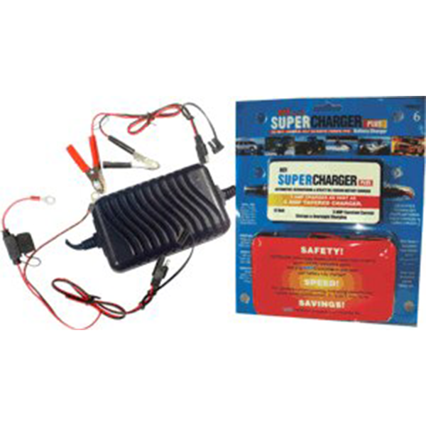
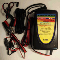
ACI Plus Fully Automatic 12 Volt 3 amp Super Charger 1206S60CC
$69.95
SKU:
1206S-60CC
Categories: ACI Super Chargers, Battery Chargers
Description
ACI Plus Fully Automatic 12 Volt 3 amp Super Charger 1206S60CC
ACI Plus Fully Automatic 12 Volt 3 amp Super Charger 1206S60CC, Super Chargers are not trickle chargers. They’re fully electronic and fully automatic. They are fully circuit and surge protected. No in-rush current to worry about when starting or stopping the charger.
They charge more quickly and will charge any 12 volt battery including ODYSSEY BATTERIES & OPTIMA BATTERIES. ACI chargers are now the recommended charger by Odyssey and Optima for storage and maintaining Odyssey Batteries and Optima Batteries. Since they are electronic, they provide a ‘true’ charge at the rated current level for the full charging cycle, thus reducing the time needed to achieve a full charge. Available in three amperage current charge ratings – 1 amp, 3 amp and 10 amp for 12 volt batteries and 4 amp for 24 volt batteries.
They will not overcharge the battery. Super Charger electronically monitors battery voltage and shuts off when voltage reading indicates battery is fully charged and then converts to “True Float Mode” and maintains the fully charged battery.
The battery can be left connected to the Super Charger for prolonged periods without affecting battery life. Days, Weeks, Months, or even Years.
They can be permanently connected to a battery with the included, fused, wire harness for easier charge connection.
They reduce sulphation during the charging cycle thus prolonging battery life.
They are smaller and lighter than conventional electrical chargers making them easier to use, and taking up less storage space.
SuperCharger Plus 3AMP Constant current charger will charge a totally flat 12 volt battery in under 4.5 hours.
Additional information
| Weight | 2 lbs |
|---|---|
| Dimensions | 8.5 × 2.5 × 10 in |
Specifications
Specifications
- 1206S60CC SuperCharger Plus
Totally Automatic Switch-Mode Battery Chargers
“Suitable for Wet-lead-acid, Sealed lead, Gel & Absorbed Mat Batteries”
Summary:
- 1206S60CC 12 Volts, 3 Amp Constant Current
(Equivalent to 6 Amp tapered charger in charging time)
– Input 115 VAC (range 90 VAC to 132 VAC)
– Suitable for U.S., Canada, other 115VAC countries & Japan (100VAC)
– Automatic Cut-off and then true Float.
– Can be left connected indefinitely without harming the battery.
– De-sulfation of battery. Increases battery life.
– UL and cUL (CSA) Listed
– Meets FCC Class B. High level of electro-magnetic interference filtering.
– Suitable for off-board application. Optional on-board inhibit can be provided.
– Many advance features described in these specifications.
– Size, 1206CC only 4 1/2” x 2 ¼” x 1 ¼” Very lightweight, only 11 ounces.
Additional Information
Additional Information
Explanation of the Features:
The advance technology of the SuperCharger Battery Chargers manufactured by ACI is fundamentally different from all other battery chargers. The conventional linear battery charger is an electrical device whereas the 1206S60CC are a lightweight sophisticated electronic device.
1. Switch-Mode Technology:
Most Battery Chargers use linear technology, which convert the 115VAC to 12 VDC at 60 Hz. This requires a large transformer, which has the disadvantage of lower efficiency resulting in higher heat generation, larger size and weight. SuperChargers transform the 115 VAC into 12 VDC at about 100,000 Hz (1667 times faster than conventional chargers), which requires a much smaller transformer and this results in a unit of smaller size, low weight and improved efficiency. The 1206S60CC use sophisticated electronic circuitry with microchips. All present day computers use switch-mode technology.
2. International Safety Approvals & Listing:
Both UL & cUL listed.
3. Input Requirements:
a) 90VAC to 132VAC
b) 47 – 63 Hz
Input AC tolerance +/- 20%. This means SuperChargers will operate satisfactorily in areas where the input voltage is low. These chargers are also suitable for every part of the world where 115 VAC is used as well as Japan where input is 100 VAC.
4. Output:
a) 3 Amp Constant Current @ 12 Volts DC (Equivalent to 6 Amp tapered charger in charging time)
b) Load Regulation @ 4%
c)Ripple Voltage: Very low @ 1%
The peak to peak ripple voltage into a resistive load is less than 200mV for the output voltage above 12 VDC.
5. Charging Cycles:
The explanation of the charging cycle is as following.
Stage 1: De-Sulfation – Deep Discharge Charging Pulse Mode: LED Flash The charger starts charging at 0.5V and gives a pulse current up to 5V. This has an effect of removing loose sulphation formed during the deep discharge state of the battery.
Stage 2: Constant Current Mode (CC): LED Yellow
The charger changes to constant current 3 Amp. When the battery voltage reaches 14.4V, the charging stage changes from CC (Constant Current) to CV (Constant Voltage) mode.
Stage 3: Cell Equalization -Constant Voltage Mode (CV): LED Yellow The chargers hold the battery at 14.4V and the current slowly reduces. When the current reaches 50% of CC, this point is called the Switching Point at which time the charger goes into “True float” mode. The Switching Point is one of the most unique features of this battery charger. It can adjust the current automatically according to battery capacity. Other chargers are not capable of adjusting the current automatically.
Stage 4: True Float – Standby Voltage Mode: LED Green The chargers maintain the battery voltage at 13.8V as the current slowly reduces to zero. Super Chargers can be left connected indefinitely without harming the battery.
Recharging: LED Yellow – If the battery voltage drops down to 12.5V, the chargers change from the current mode to Constant Current mode and restarts charging. The charging cycle will go through Stage 2 to Stage 4.
6. Two colours and function in one LED:
LED is used to show the charging status. When the LED is Yellow, the charger is in charging or recharging mode and the current is 3 A constant. When the LED turns Green, the charger is in Standby mode and no current (zero) is flowing.
7. Protection:
a)Reverse polarity protection – provided
b)Short circuit protection – provided
c)Over-Voltage Protection – provided
d)Over current protection – provided
e)AC Surge Protection – provided
f)Soft start and stop: Starts and stops gradually.
No sudden in-rush of current. This protects both the battery and all other circuits connected to the charger.
8. De-sulfation of battery: The charger will remove loose sulfation, which increases battery life. (Hard sulfation cannot be reversed).
9. Electromagnetic Interference (EMI): The charger will not generate excessive radiated or conducted emissions. No interference with TV, radio, computer or other electronic equipment.
Meets FCC Class B. 10. On-board Feature: Optional – The optional model has a third output wire, which provides an Inhibit signal that will prohibit the operation of the vehicle’s motor controller whenever the charger is plugged to an AC source.
11. Inhibit signal: The Inhibit signal is an open circuit output, leakage of less than 5 microAmp, when the charger is not connected to an AC source. This signal will be less than 50 mV DC while sinking 10 mA when the charger is connected to an AC source.
12. Size & weight:
1206CC only 4 1/2” x 2 ¼” x 1 ¼” Very lightweight, only 11 ounces.
